Technical Information Fig. 116 'MF' Series


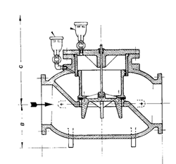
The Type ‘MF’ Reducing Valve is hydraulically operated, single seated, piston actuated, diaphragm pilot controlled and spring regulated.
Automatically reduces higher and fluctuating inlet pressure to constant outlet pressures regardless of the flow demands.
The diaphragm pilot control closes when outlet setting is attained, diverting inlet pressure to the piston which closes the main valve at the rate determined by the flow restrictor. The "V-Ported" valve guide eliminates closing ‘slam.’ Under operating conditions the main valve establishes a throttling position as determined by the pilot control.
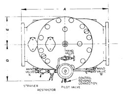
Dimensions (mm)
| Valve Size | 80 | 100 | 150 | 200 | 250 | 300 | 400 | 450 | 500 | 610 | 750 |
|---|---|---|---|---|---|---|---|---|---|---|---|
| 'A' | 295 | 355 | 445 | 610 | 760 | 915 | 1220 | 1370 | 1525 | 1675 | 2030 |
| 'B' | 95 | 140 | 165 | 205 | 230 | 330 | 400 | 430 | 500 | 510 | 610 |
| 'C' | 360 | 510 | 560 | 690 | 720 | 760 | 1000 | 900 | 850 | 1020 | 1140 |
| 'D' | 150 | 165 | 200 | 300 | 300 | 400 | 500 | 560 | 600 | 660 | 770 |
| 'E' | 150 | 150 | 200 | 300 | 300 | 300 | 360 | 400 | 450 | 490 | 620 |
| Mass / kg | 42 | 65 | 120 | 250 | 450 | 700 | 1350 | 1700 | 2100 | 2700 | 5000 |
Specifications
| Flanges | As 2129 Tables E & F |
|---|---|
| Working Pressure | Table E 1400 kPa Table F 2100 kPa |
| Adjustable Ranges | 0-115, 70-230, 200-700, 600-1100, 700-1500 kPa |
| Temperature Range | Water 5 - 60oC |
Materials
| Body & Cover | Cast Iron AS 1830/T250 |
|---|---|
| Valve Carrier | 150-300mm Bronze AS 1565/836B 400-750mm Cast Iron AS 1830/T250 |
| Internal Parts | Bronze AS 1565/836B Grade 316 Stainless Steel |
| Valve Disc and Seals | Polyurethane Neoprene |
| Pilot Valve | Bronze AS 1565/836B Grade 316 Stainless Steel |
| Coatings | Epoxy Paint Int. & Ext. (0.5mm min. D.F.T.) |
Flows (I/sec)
| Valve Size | 100 | 150 | 200 | 250 | 300 | 400 | 450 | 500 | 610 | 750 |
|---|---|---|---|---|---|---|---|---|---|---|
| Recommended Min | 2 | 4 | 10 | 15 | 22 | 39 | 48 | 60 | 86 | 136 |
| Normal Max. P/line Vel. 6m/sec. |
40 | 80 | 190 | 300 | 430 | 770 | 970 | 1190 | 1720 | 2730 |
| Occasional Max. P/line Vel. 8m/sec. |
55 | 110 | 250 | 400 | 570 | 1020 | 1300 | 1590 | 2290 | 3640 |
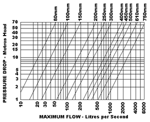
The life of any valve will be shortened by high velocity flows.
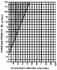
Cavitation may occur if the intersection point of inlet and outlet pressures fall within the shaded zone.
The siting of a reducing valve to obtain a higher outlet pressure reduces the risk of cavitation and the need for special trim materials.
When minimum flows are anticipated we recommend that a direct-acting reducing valve be installed in parallel to handle the smaller flows.


