


Technical Information - Fig. 119
Operation:
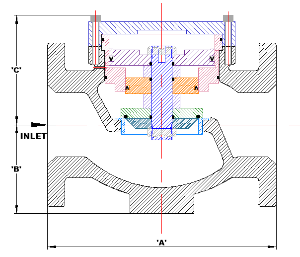
The upstream pressure is introduced below the valve disc, which is opposed to atmospheric pressure via a vent port above the inlet balancing piston.
The downstream pressure is introduced above the control piston, which is sized to a fixed ratio of the area of the valve disc, and also opposed to atmospheric pressure via the vent port.
The valve will then modulate the flow to maintain a fixed relationship (eg. 5:1) between the upstream and downstream pressures, governed by the ratio of the respective areas of the valve disc and the control piston.
The Fig 119 ratio reducing valves are a type of pressure regulator that reduce high inlet pressure to a lower, stable outlet pressure at a fixed ratio.
Ratio valves provide consistent and accurate pressure reduction, ensuring that the downstream pressure remains stable and predictable.
Dimensions (mm)
|
Valve Size |
80 |
100 |
125 |
150 |
|
‘A’ |
292 |
356 |
356 |
445 |
|
‘B’ |
105 |
140 |
140 |
165 |
|
‘C’ |
160 |
170 |
170 |
250 |
Specifications
| Material | SG Iron, Cast Steel or Stainless Steel |
|---|---|
| Connections | 25-50mm Screwed or 40-150mm Flanged |
| Working Pressure | 2600 kPa (Can be manufactured for higher pressures) |
| Ratio's | 5:1, 4:1, 3:1, 2:1 - Custom Ratios Available |
| Temperature Range (Nitrile seals) | 0oC - 80oC |
| Temperature Range (Viton seals) | Above 80oC |