


Technical Information Fig No. A72
The Fig. A72 range are of all stainless-steel construction making it suitable for a wide range of applications.
The hydraulically balanced spindle enables the valve to maintain a constant upstream (relieving) pressure regardless of downstream pressure fluctuations.
It is an ideal valve to employ where a direct spring-loaded type of valve is too insensitive to pressure flow variations.
- Protects systems from overpressure.
- Maintains constant pressure in a system by discharging excess product to atmosphere or container.
- Reduces cavitation or other damage to pumps by bypassing back to suction at a given pressure.
For water, oil, gas or chemical services.
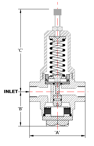
Dimensions (mm)
|
Valve Size (mm) |
A |
A |
B |
C |
kg |
|
10 |
93 |
- |
58 |
140 |
2 |
|
15 |
93 |
135 |
58 |
140 |
2 |
|
20 |
93 |
156 |
58 |
140 |
2 |
|
25 |
114 |
152 |
75 |
215 |
6 |
|
32 |
165 |
214 |
93 |
215 |
7 |
|
40 |
176 |
214 |
116 |
300 |
10 |
|
50 |
176 |
214 |
116 |
300 |
10.5 |
Specifications
| Connections | BSP, NPT or Flanged |
|---|---|
| Adjustable Ranges | 0-230, 200-700, 500-1600 kPa, 1200-2200 kPa |
| Temperature Ranges | Nitrile - Up to 90oC or Viton - Above 90oC |
Want to modify / customise this valve? Contact Us today to discuss your requirements.