
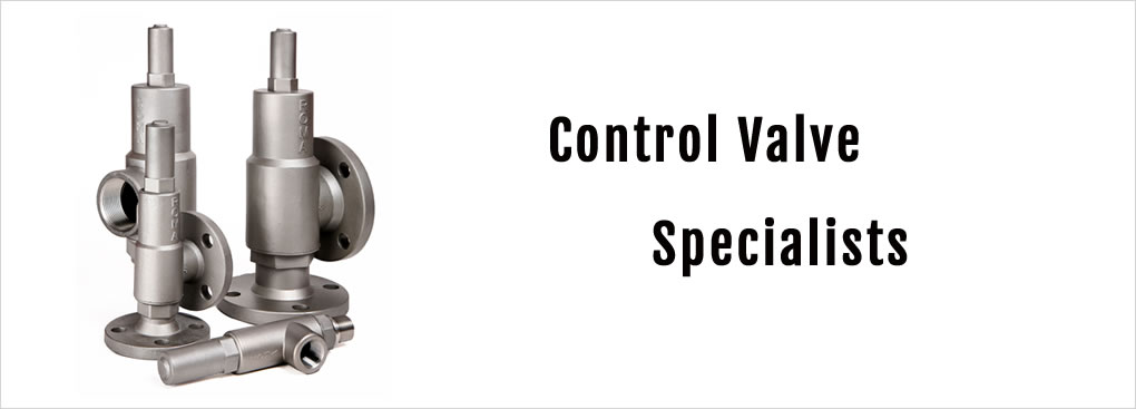
Pressure Control Valve Specialists
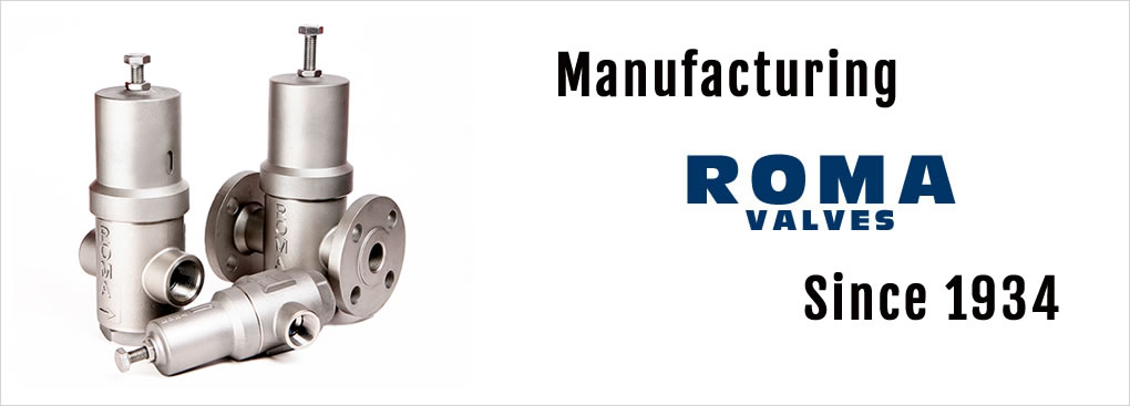
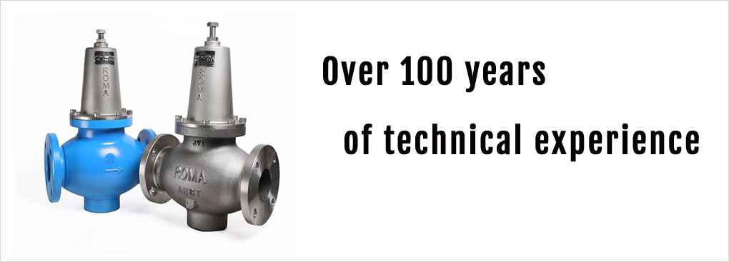
Manufacturing and designing Roma Valves since 1934
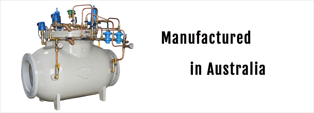
Calorex Australia is one of Australia's leading manufacturers and suppliers of pressure control valves.
We design and manufacture valves for a wide range of industrial, commercial, water supply, mining, irrigation, sewerage, and water treatment applications.
Our extensive product range includes pressure relief valves, pressure reducing valves, back pressure valves, float valves, and more — all engineered for reliability, performance, and long service life.
Calorex also provides comprehensive technical support, including valve testing, spare parts, servicing, and reconditioning, ensuring every product continues to perform to the highest standards.
Categories
We’ve been manufacturing and designing valves since 1934. Our valves can be produced in a range of materials including Hastelloy-C, Duplex 2205, Super Duplex and 316 Stainless Steel. Our Featured Valve Categories are below or view our entire category range of valves
Featured Categories
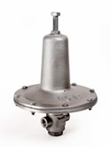
Pressure Reducing
Valves
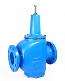
Also known as regulating or pressure limiting valves.
Direct acting, pilot operated or ratio reducing.
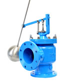
Pressure Relief
Valves
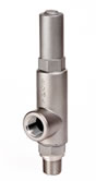
Direct acting or pilot operated.
We also have a range of back-pressure, sustaining or surplus valves.
Float Valves (Level Control Valves)
Pilot operated, Equilibrium and Remote Float. Angle or straight through body style
VIEW RANGECustom
Valves
We can build or modify a valve to suit your requirements.
Please contact us.
You can rely on our 90 years of technical experience for the selection and application of our standard valves, or for the design and manufacture of custom valves.