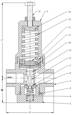
Technical Information - Fig No. 514
The Figure 514 Pressure Reducing Valve is direct acting, single seated, piston controlled and spring regulated.
The Valve Disc assembly is in hydraulic balance and therefore the downstream pressure setting is not affected by varying upstream pressures.
The downstream pressure is directed to the piston, which causes the valve to modulate the flow to achieve a regulated output pressure.
The valve is suitable for drop-tight installations of water, air, gas, oil and chemical services.
Dimensions (mm)
| Valve Size (mm) | 8 | 10 | 15 | 20 | 25 | 32 | 40 | 50 |
|---|---|---|---|---|---|---|---|---|
| A (scd) | 50 | 93 | 93 | 93 | 114 | 140 | 170 | 170 |
| A (flgd) | - | - | 135 | 156 | 214 | 214 | 214 | 214 |
| B | 33 | 45 | 45 | 45 | 61 | 75 | 88 | 88 |
| C | 135 | 135 | 135 | 135 | 204 | 210 | 258 | 258 |
| Mass / Kg | 1 | 2 | 2 | 2 | 6 | 7 | 10 | 10 |
Specifications
| Connections | BSP/NPT, Flanged |
|---|---|
| Working Pressure | 4000 kPa Maximum |
| Adjustable Ranges | 100-300, 200-700, 500-1600kPa, and higher |
| Temp. Range | Nitrile seals: -10oC - 90oC Viton seals: -10oC - 180oC |
Materials
| Item | Description | Material |
|---|---|---|
| 15 | Adjusting Screw | SS316 |
| 14 | Upper Spring Pad | SS316 |
| 13 | Regulating Spring | SS304 |
| 12 | Lower Spring Pad | SS316 |
| 11 | Piston | SS316 |
| 10 | Piston 'U' Seal | Nitrile or Viton |
| 9 | Spindle 'O' Ring | Nitrile or Viton |
| 8 | Valve Spindle | SS316 |
| 7 | Disc Seal | Nitrile or Viton |
| 6 | Retaining Disc | SS |
| 5 | Cap Gasket | Nitrile or Viton |
| 4 | Return Spring | SS304 |
| 3 | Spring Cage | SS316 |
| 2 | Cap | SS316 |
| 1 | Body | SS316 |
Want to modify / customise this valve? Contact Us today to discuss your requirements.


